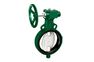
Salient Features of Butterfly Valves
- Design Standard IS 13095 / BSEN 593 (BS 5155).
- Wafer Type.
- Gear Operated.
- S.G Iron construction.
- S.G Iron disc which is accurately guided between the two stems.
- Integrally molded rubber lining (EPDM / Nitrile / Neoprene* / Viton* / Silicon*) as per requirement which provides seating to the valve disc, as a primary seal to the stem and gasket joint with matching pipe flanges.
- Two Piece Stem design which is precisely guided between the PTFE / Bronze bushes.
- Compatible to sandwich between flanges as per BS 10 Table D, E, F,H, DIN, PN10, PN16, PN25, PN40, ASA 150, ASA 300, IS 778, IS 6392 Table 17 and IS 1538.
*Valves with Neoprene / Viton / Silicon lining can also be provided at nominal extra cost.
PN10 –
Test Pressure (Hydrostatic) :
Shell : 15 bar (220 psig)
Seat : 11 bar (160 psig).
Maximum Working Pressure : 10 bar (140 psig)
Maximum Working Temperature : 90°C
PN16 –
Test Pressure (Hydrostatic) :
Shell : 24 bar (340 psig)
Seat : 17.6 bar (250 psig)
Maximum Working Pressure : 16 bar (230 psig)
Maximum Working Temperature : 90°C
Materials
| P.No. | Name of Part | Material of Construction | Specification | Qty. |
|---|---|---|---|---|
| 1 | Gear Box Assembly | – – – | – – – | 1 |
| 2 | Gasket | Steam Jointing Sheet | IS2712 Gr. W/3 | 1 |
| 3 | Packing Bush | PTFE / Bronze | BSEN 12086-1 / IS 318 Gr. LTB 2 | 1 |
| 4 | Upper Stem | Stainless Steel | ASTM A 276 Type 410 | 1 |
| 5 | Body | S.G. Iron | ASTM A 536 / IS 1865 | 1 |
| 6 | Disc | S. G. Iron | ASTM A 536 / IS 1865 | 1 |
| 7 | Taper Pin (Optional) | Stainless Steel | ASTM A 276 Type 410 | 1 |
| 8 | Bush | PTFE / Bronze | BSEN 12086-1 / IS 318 Gr. LTB 2 | 1 |
| 9 | Lower Stem | Stainless Steel | ASTM A 276 Type 410 | 1 |
| 10 | ‘O’ Ring | Nitrile Rubber | IS 5192 – 1 | 1 |
| 11 | Dowel Pin | Spring Steel | – – – | 1 |
| 12 | C – Sunk Screw & Nuts | Carbon Steel | – – – | 4 Each |
| 13 | Handwheel | Cast Iron / Sheet Metal | IS 210 Gr. FG 200 / – – – | 1 |
| 14 | Body Lining | EPDM / Nitrile | IS 5192 – 1 | 1 |
| 15 | Name Plate | Aluminium | – – – | 1 |
Sizes / Dimensions
| Size (Inches) | Size (mm) | A ±1.5 | ØB | C ~ | D ~ |
|---|---|---|---|---|---|
| 8 | 200 | 57.5 | 199.6 | 180 | 295 |
| 10 | 250 | 65.5 | 250 | 220 | 320 |
| 12 | 300 | 77.5 | 298 | 250 | 344 |
| 14# | 350 | 85 | 350 | 280 | 380 |
| 16# | 400 | 96 | 392 | 300 | 410 |
| 18# | 450 | 108 | 440 | 330 | 466 |
| 24# | 600 | 146.5 | 590 | 440 | 610 |


 FSC
FSC